How I fix the error P0335 Crankshaft position sensor circuit fault Ford Fiesta 1.3 rev/min gauge not working
P0335 Crankshaft position sensor circuit fault.
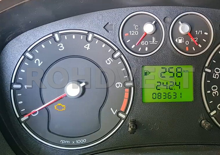
The car came to me with a defective tachometer.
The tachometer did not indicate the engine speed. When starting the engine, the needle rose above 1000 rev/min, after which it dropped to zero, it randomly worked for a few seconds, but did not indicate the correct rev/min.
The owner told me that he had a problem with the camshaft sensor, which he had changed.
He also told me that the pins on the instrument clusters connector were resoldered, but this operation did not fix the problem.
Watch my youtube video for more detailed steps.
Tools used in this video:
Back Probe Kit Alligator Clip to 4mm Banana Plug

I connected the Autel diagnostic tablet to scan the error codes and they were the following:
P0335 Crankshaft Position Sensor circuit fault
P0704 Cluch switch – implausible signal and another P0704 Clutch switch input circuit malfunction

I also scanned all the modules on the car and the errors stored on the instruments were: P2479, related to the handbrake, and U2196 Invalid data for engine rev/min.
The U symbol means communication error between the car modules, in this case between ECU and the instrument clusters. I deleted the error codes, only P2479 remained until the next start of the car. The U2479 appeared again after the tachometer needle dropped to zero.
The problem was still there and could be caused by the crankshaft position sensor wiring, the crankshaft position sensor itself, or a faulty ECM.

ECU Live data info show the correct engine speed. This information misled me into thinking that it was still a problem with the instruments.

To totally eliminate the instrument clusters from the equation I tested the tachometer needle from Autel tablet, this test can be activate manually by pushing the left instrument clusters button and turning the ignition on at the same time. Keep pressing the button until the word “test” appears on the display. After that release the button. To exit from test mode you must turn the ignition off.

Even more, I disassembled the instrument cluster and rechecked the solders on the connector. The connector pins were properly soldered to the board. I put the cluster instrument in place and focused my attention on the Crankshaft Position Sensor and the wires between it and the ECM.

To remove the Crankshaft Position Sensor I dismantled several components of the air intake system in the engine.
The sensor is located above the starter motor, in the engine block, it has a 2-pin plug and a shielded cable, for protection against interference.
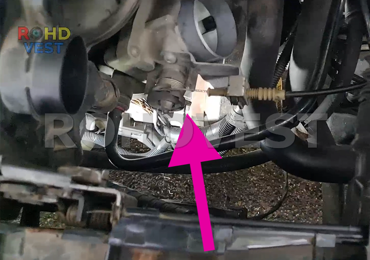

The connector is released by pressing the metal part towards the body of the connector. I tried a new sensor, bought for about 15 dollars. The problem was not fixed.
I also released the ECM from the support in which it was attached near the battery and disconnected the plug. A real headache because the connector is attached to the ECM plug with a rivet. With a drill I drilled the rivet and released the connector.


I measured the resistance of the Crankshaft Position Sensor, according to the technical specifications it must be 420 ohm. The resulting value was 422 ohms.

I measured the continuity between pin 1 of the sensor and pin 37 of the ECM, the white / red wire, the continuity was fine
There was also continuity between pin 2 of the sensor and pin 26 of the ECM, the brown/red wire was fine.
I checked that there was no short circuit between the two wires of the sensor and that there was no short circuit with the ground of the car. Everything was fine.

I connected the DIY DS 138 oscilloscope to check if the sensor was sending a signal to the ECM. The signal was present.


At this moment I noticed that the tachometer needle worked if I pressed the oscilloscope probe in pin 37 of the ECM. I disconnected the oscilloscope and just pressed the needle in pin 37 and the tachometer worked.
Initially I wanted to remove the pin from the ECM connector and change it, but I didn’t realize how to remove the pins from the connector socket on this type of ECM.
Next, I disassembled the ECM and resoldered the connector pins on the board.


I checked in the test points if the sensor signal reaches the board. The signal was present at the test point at pin 37 and 26.

I made a backup of the flash memory and eeprom of the ECM, I put everything back and it seemed that the tachometer started working again.

Thanks for reading my post, don’t forget to subscribe to the my youtube channel, share and like the videos. If you really appreciate the work done on my youtube channel, you can support me by pressing the “THANKS” button.
Have a nice day.
The link with the information about the P1000 error is here: Ford Motor Company Driving Cycle
You Tube Members
Subscribe to my youtube channel

Good morning
I wanted to say a big thank you for your video and explanation
I had this problem with a Ford Fiesta
Thank you so much
Bonjour
Je revient vert vous car mon problème na pas disparue avec erreur P0335
J’ai remis des fils a l’extérieur du boitier pour éliminé les câblage mes toujours le capteur en défaut après démarrage.
Il se peux que le ECM et endommagé ?
Merci