VW PASSAT B6 Passat B6 / 3C Inner Tail Light – Skyline lights / part 1
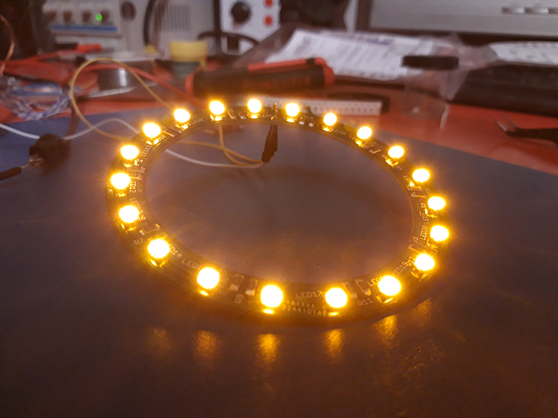
Here you can find some information about VW Passat B6 Inner Tail Light (Skyline lights) .
In the video I will show you how to order the VW Passat B6 Inner Tail Light printed circuits board for skyline leds rings.
At the bottom of the page you can download the gerber project. You can upload it to www.jlcpcb.com, www.pcbway.com or other sites for pcb manufacturing. On the www.pcbway.com you can place the order from here.
 In the archive you have a pdf file for ironing method.
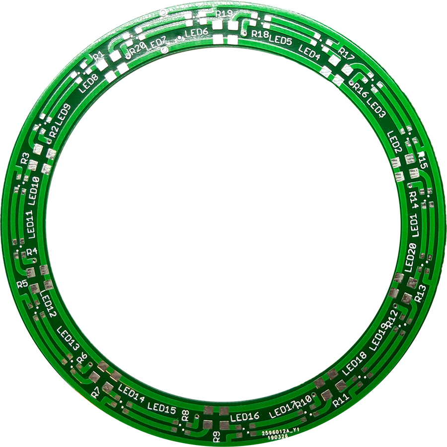
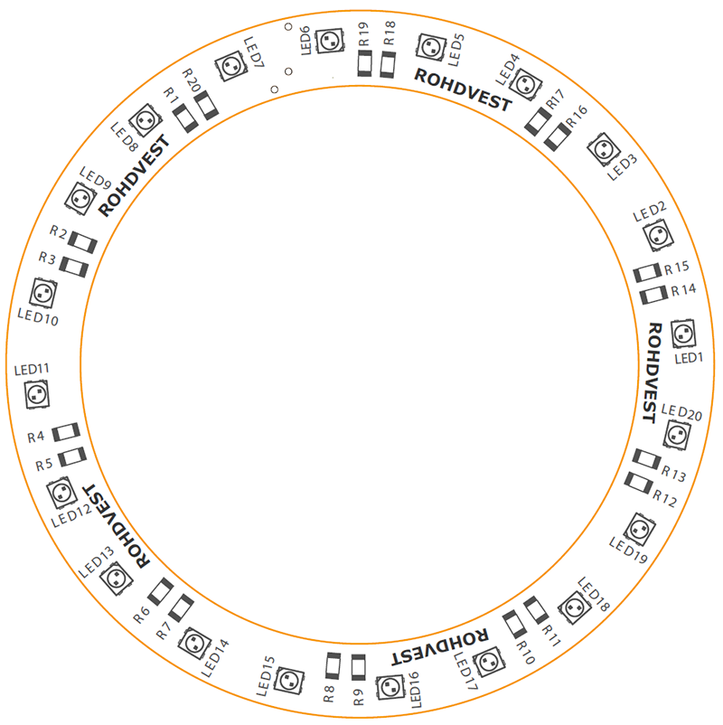
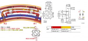
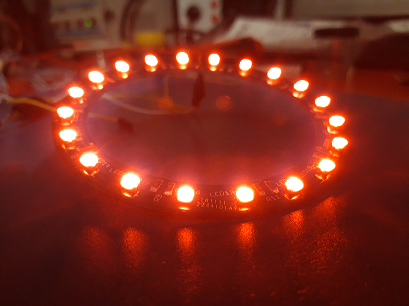
I tested it with two-color PLCC4 50mA leds from China and 1206 smd resistors. I have a ring from the original lamp and I compared the brightness under the same voltage. The brightness of the LEDs depends on the type of LED you use and of course the value of the resistors.
I used 360 ohm 1/4W resistors for the red leds and 220 ohm 1/4W resistors for the yellow leds, but as I said, I compared the brightness of the rings with the original lamp brightness
Leds and resistors
LINK 1 or LINK 2 for Chinese leds which I used for testing
OSRAM LSY T67B Leds – Original OSRAM leds
TUTORIAL from http://www.angelico.ca/
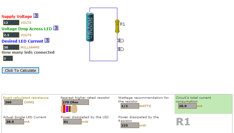
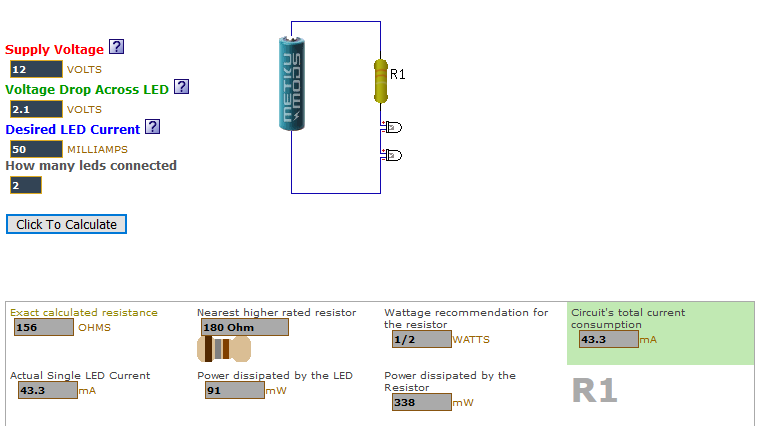
RESISTORS CALCULATOR: http://ledcalc.com/
30mA leds
50 mA leds
The password of the archive is: rohdvest.ro

hi!!! tell me pls i ordered on JLCPCB PCB Prototype skyline 4_2019-07-16_Y2
tell me pls if i will be install Original OSRAM leds 30mA what R for red and R for yellow i need to install compare the brightness of the rings with the original lamp brightness??
I saw that you used 360 ohm 1/4W resistors for the red leds and 220 ohm 1/4W resistors for the yellow leds for Leds 50mA
maybe you know parameters for original 30mA OSRAM??
Thanks alot for answer for me on email Lordx2008@gmail.com
I didn’t try yet with original leds. Somebody told me he used for original osram leds 100 ohm resistor for 4 yellow leds and 180 ohm for 4 red leds. My schematic is with 2 leds in serie not 4.
salut am descarcat fisierul pdf si imi cere o parola ? ce trebuie sa fac ?
“The password of the archive is: rohdvest.ro”
Hi, there are no brake lights in this project?
The led are bicolor: red for tail lights and break, yellow for turning signals
Hi, friend.
Sorry if my English is not very good, I am using the translator as I do not speak English.
First of all, thank you for the contribution, I have done a good job.
Following your tutorial, I ordered the printed circuits from jlcpcb.com and used the templates you provide.
And the components that I used were the following, these led https://a.aliexpress.com/_uAUse8
And these resistors https://a.aliexpress.com/_v3Ke2k for the red LEDs for 360 and for yellow LEDs for 220.
My question is the following, before installing them in the car I wanted to test them that they worked correctly, and to test them I used a 12v direct current and 5A power supply.
The point is that when I turned them on I noticed that both the LEDs and the resistors got quite hot, in fact if I leave it on they start to smoke a little. The welds are well done, and I have not seen any short circuit on the board.
What could this be due to? Is it possible that I was wrong in the resistors? Or is the power supply that I use the wrong one?
A greeting and thanks in advance
Hi. Send me a picture on email with your resistors to see what is writes on them. The leds are on? I think now you can use 330 ohms for red leds and 390 for yellow.
Hi, friend.
Thanks for answering, because for the red LEDs I use the ones that put in the 360 resistance and for the yellow ones I use the one that puts 220. If you want write me to the email that is Dani.vazquez89@hotmail.com and I will send you photos and videos of the operation.
Thank you very much and greetings.
I saw your pictures. You put 22 ohms and 36 ohms resistors. 220 code is 22 ohms and 360 code is 36 ohms. The correct smd codes are 221 or 2200 and 361 or 3600. Your resistors are 10 time smaller and that is the reason why the leds are smoking.
hii my freand can u send me pictures please of the rezistors and video over my email please verbatonvio@yahoo.co.uk thanks
Hello, please the original file the eagle software. I have an idea to redo it for my purpose. thank you
someone can help me with the gerber file for board? i dont know how do the files to gerber. Thank you
Hey man, nice tutorial. But ehat resistors would you recommend, im guessing you tried a few. Thanks
Hello, thank you for your great job :). Can you send me the circuit please? I just want to see the schematic from this
Thank you in advance!
Hello.
First of all congratulations for the excellent work.
I question if you can do the same thing for the valeo tail lights of the VW golf 5, and how much would that job cost.
Best Regards
Vieira
https://rohdvest.ro/2020/12/13/lights-4/vw-golf-5-plus-skyline-led-rings-pcb-project-gerber-archive/
For white and red led do you know which led is used to original?
https://www.osram.com/
Is it posible to do all like this but to be dynamic?
https://ali.ski/hm1Ax8
Multumesc pentru proiect! https://www.youtube.com/shorts/1tDgNRcBDoI
Hi there,
Is it possible to order these fully ready to use from PCB way?
It looks like it is, but I’m unsure about how to go about it?
Salut, de unde ai alimentat +12V pentru alimentare? Direct din triple?
Hello. I ordered this but i don’t know hot to do conection . Can you help me?
Hello!
can you tell how to mount this module to the skyline?
Module dinamyc
Hello. Can you buy just the mounting plates? and is it possible to ship to Poland
I am in the midst of ordering these now :). from pcbway. the preview shows the pcb disc with no hole in the middle ? is this correct?. and do i need to sodler the leads on when they arrive.?
Thank you so much for your file btw i’m deffo buying you a coffee 🙂
hi buddy what diode do you reccomend to use for the supplies from brake and parking light feed?
how to connect vcc cable or ground (amber or yellow)